A separate contact head. Assembly from the rear. Carefully formed plunger guidance. Explore the engineering described in Equip-Test’s US patent and what it means when selecting a test probe.
The drawings and explanations below describe patent embodiments. Dimensions, materials and ratings for your selected SuperProbes reference are confirmed in its product specification.
01 / ASSEMBLY
A different sequence opens up the design.
The head and plunger are manufactured separately. The plunger can therefore pass through a preformed guide before a wider head is attached. The manufacturing sequence in claim 1 follows four steps.
Insert the plunger
Feed it through the rear of the barrel. Its narrow end projects through the front guide while its broadened rear portion remains inside.
Fit the contact head
Connect the separate head to the exposed plunger end by press fitting or shrink fitting.
Insert the spring
Feed the spring through the rear until it bears against the broadened portion of the plunger.
Close the rear
Fit the plug to close the barrel and preload the spring.
The front guide can be formed before assembly. A larger contact head no longer has to pass through that guide, giving the design more freedom in guide length and head geometry.
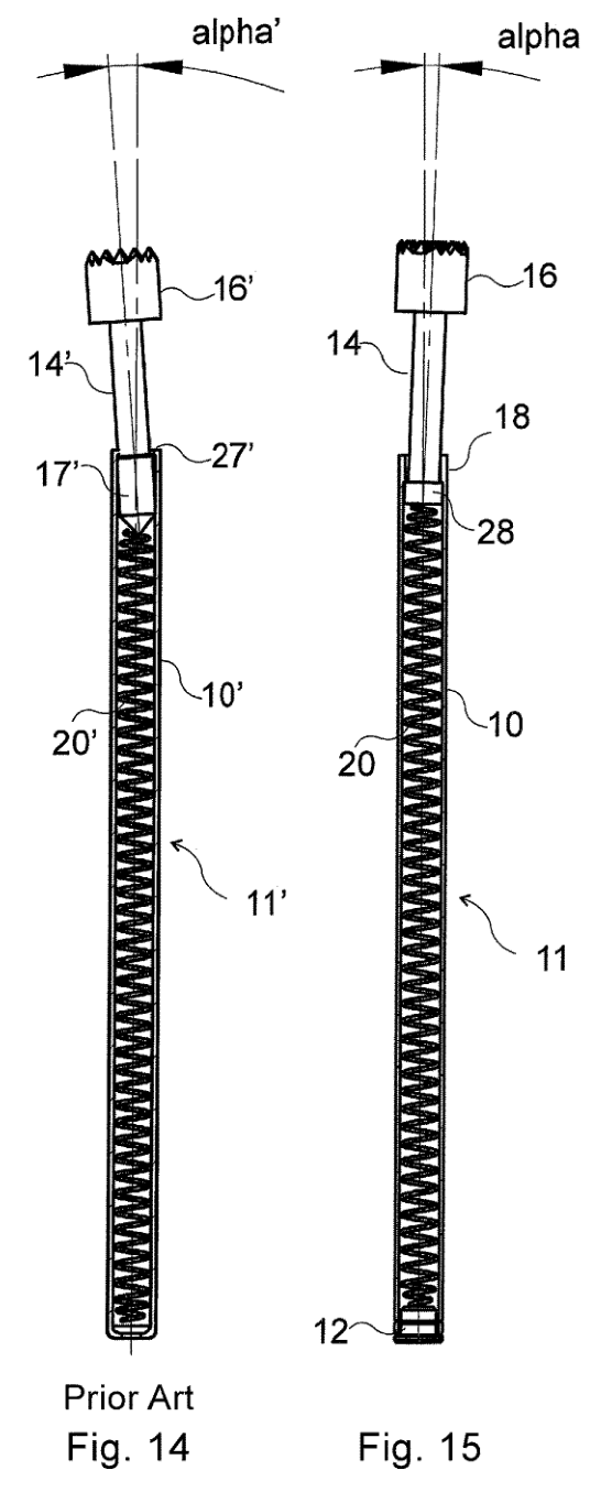
The patent compares a conventional rim-type retaining feature with an extended guiding flange. The extended guide provides lateral support along the plunger shaft.
In the described close-fitting arrangement, guidance occurs at two surfaces: the shaft within the front guide and the broadened rear portion within the barrel. Their geometry and clearances influence angular play at the tip.
Reduced play helps the tip reach its intended test point. The patent also explains how wear in a conventional guide can increase play over time.
Assess tip geometry, exposed plunger length, fixture alignment, board position and working stroke together. Lower wobble supports smaller-pad contacting; it does not define a universal minimum pad size.
Original figures 14 and 15, US 11,268,982 B2. The angles are illustrative and have no numerical values assigned in these drawings.
03 / ELECTRICAL CONTACT
Mechanical contact shapes the current path.
Plunger-to-barrel contact
The patent describes how a larger, more consistent contact surface between plunger and barrel can improve conduction. The spring supplies contact force, while the conductive plunger and barrel also provide a current path.
One optional embodiment uses an inclined face on the broadened plunger end. Spring loading biases the plunger against the barrel, increasing their contact area. The patent associates this arrangement with reduced resistance and improved current carrying capability.
Current rating, temperature rise and contact resistance must be established for the chosen reference and operating conditions. The patent’s example applications are not universal SuperProbes ratings.
04 / TIP GEOMETRY & MATERIALS
Choose the contact surface independently.
Separating the head from the plunger allows each component to use a material suited to its role. The patent describes a palladium-alloy head attached to a plunger made from another material.
This concentrates the specialist material at the contacting end. Manufacturing the components from separate blanks can also reduce machining waste, particularly when the head is wider than the shaft.
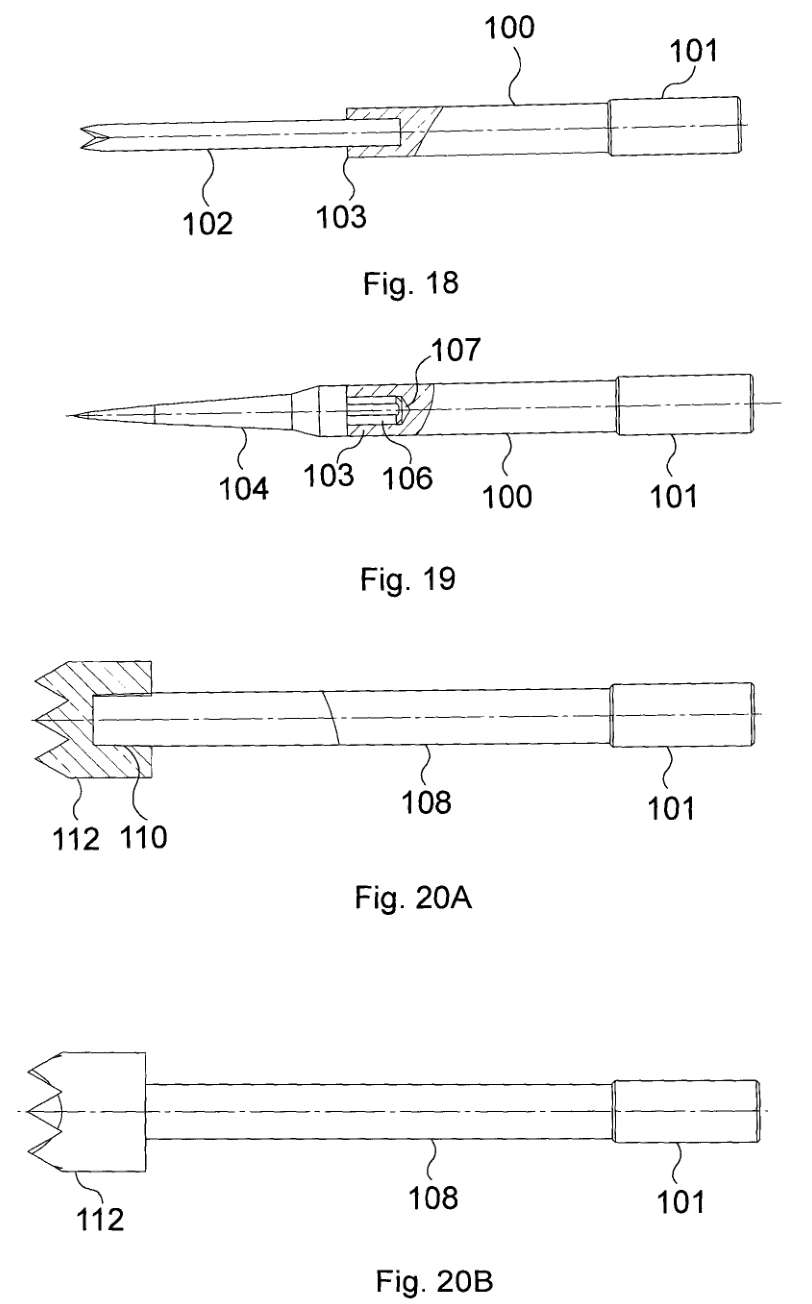
The illustrated embodiments include pointed, multi-tip, rounded and wider heads. These are design possibilities; the available tip styles and materials depend on the selected product reference.
Press fitting uses controlled interference between mating parts. Shrink fitting uses thermal expansion and contraction to establish the fit. These are permanent connections, not a field-changeable tip mechanism.
Original figures 18–20B. Different head geometries and joint arrangements described in the patent.
05 / ENGINEERING VALIDATION
From construction to production evidence.
The patent describes measuring assembly force during press fitting and checking spring force and conductivity in a switch-probe manufacturing example. These show how the assembly can be checked; they do not establish a testing protocol for every current SuperProbes reference.
Rear assembly, permanent head attachment and described guidance arrangements
The construction of your selected reference
Equip-Test indicative values
Approximately 1° wobble and 5 mΩ contact resistance, as supplied by Equip-Test
Measurement conditions, working stroke and reference-specific data
Application evaluation
Actual contacting performance on your board and fixture
First pass yield, retest rate, resistance stability and maintenance interval
The patent explains engineering principles. The indicative performance figures on this site are separate Equip-Test data, not numerical results established by the patent. Lifetime and savings depend on the application.
Bring the details that decide the contact.
Share the existing probe reference, tip style, pad size, board finish, pitch, working stroke and spring force in N (oz-force). Add the test current, fixture alignment information and the contacting problem you want to solve.